

Flume drain
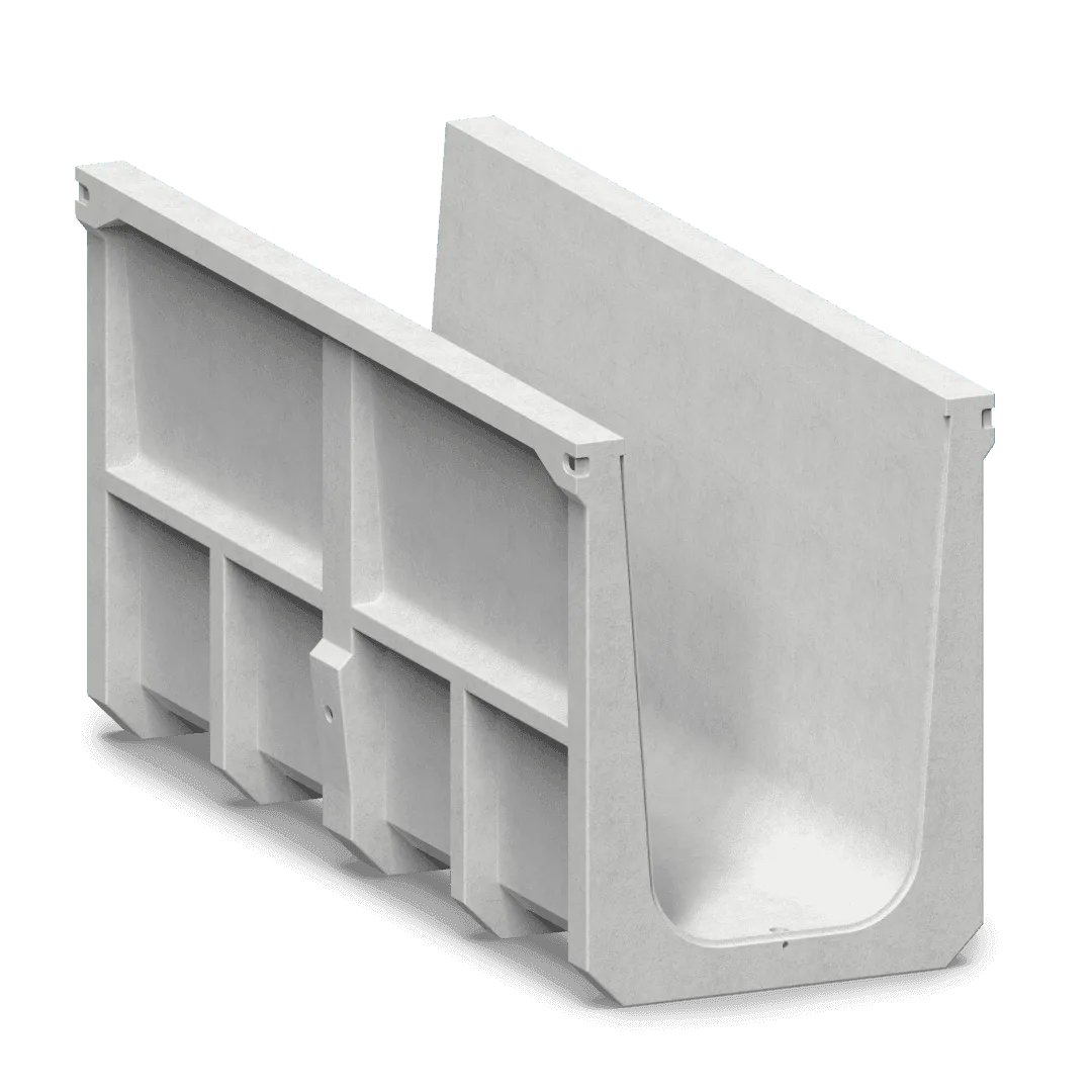
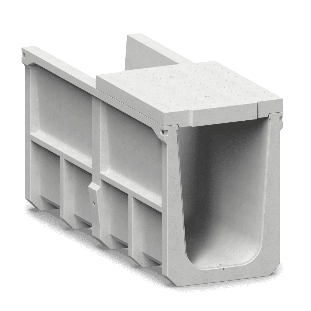
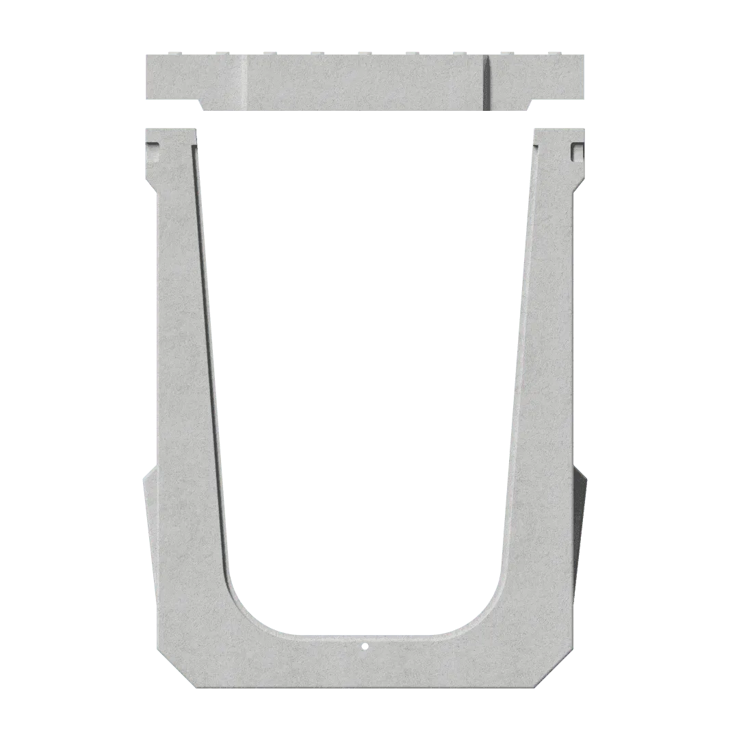
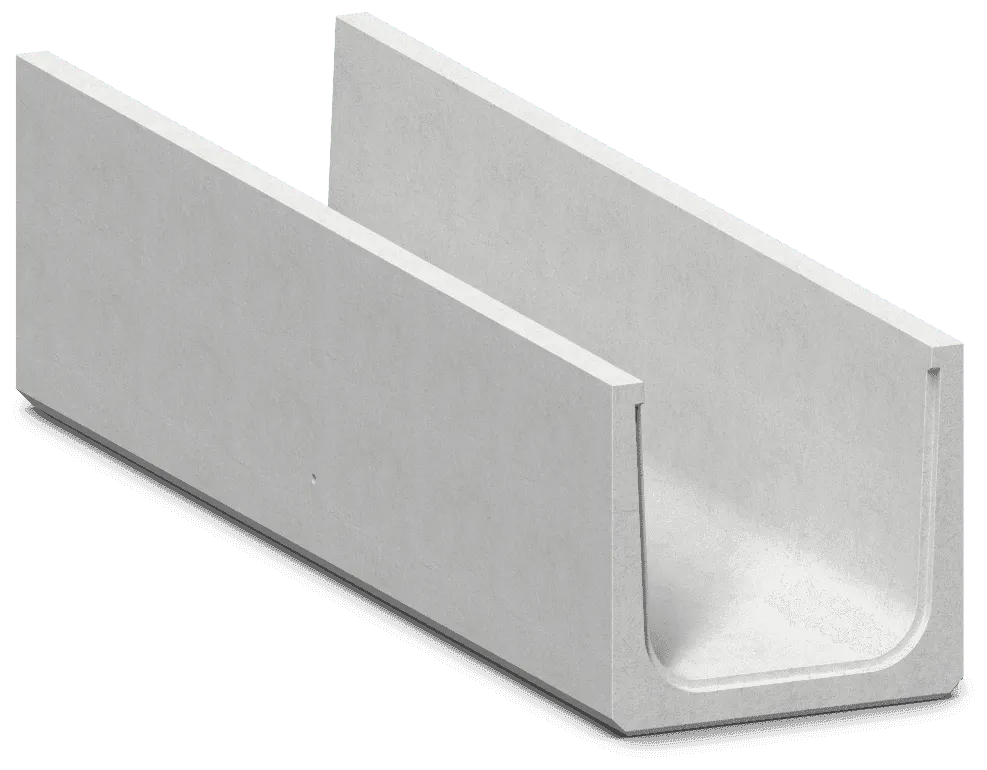
FT Flume Precast U Drain
Precision-cast flume drain channel built for controlled water flow in irrigation, agricultural, and infrastructure projects.
- 01 Size range
- B 600–2000 mm × H 900–1800 mm
- 02 Unit length L
- 2000 mm
- 03 Load rating
- Live load 1 T/m² (10 kN/m²)
- 04 Standard sizes
- 104
Overview
The FT Flume Precast U Drain is purpose-built for projects that demand precise, controlled water flow across longer channel runs. With a hydraulically optimised profile and dense RCC construction, it performs reliably in irrigation networks, agricultural canals, and roadside stormwater flumes — even in challenging terrain and high-rainfall conditions.
- F/01
Durable Material
Cast from high-grade RCC with a smooth internal finish for reduced friction and optimal water velocity.
- F/02
Efficient Design
Flume profile maintains controlled, consistent flow direction — ideal for irrigation and canal lining.
- F/03
Dual Application
Used in agricultural irrigation channels, roadside flumes, and stormwater collection in sloped terrain.
Configure in 3D
Pick a standard size, turn the FT Flume Precast U Drain around and add it straight to your quote.
FT
FT Flume Precast U Drain
800 × 1400 mm · L 2000 mm
Casting 3D model…
Dimension tables
All dimensions in mm, transcribed from the published tables. Hover or focus a column letter to see what it measures.
T/01 · 13 rows · mm
H : 900 (H1: 995)
| Internal clear width of the channel at the top, between the inner faces of the two side walls (front view). | Overall external width at the top of the unit, across both side walls (front view shows B1 = t1 + B + t1). | Appears to be the internal clear width at the bottom of the channel, where the tapered inner walls meet the curved floor — narrower than B because the walls taper inward towards the base. The front-view extension lines are not fully explicit. | Overall external width at the bottom of the unit, across the outer faces of the lower side walls (front view). In the typical section the bedding extends 50 mm beyond D on each side and the excavation base 300 mm beyond D on each side. | Actions |
|---|---|---|---|---|
| 600 | 780 | 465 | 740 | 3D |
| 700 | 880 | 565 | 840 | 3D |
| 800 | 980 | 665 | 940 | 3D |
| 900 | 1080 | 765 | 1040 | 3D |
| 1000 | 1180 | 865 | 1140 | 3D |
| 1100 | 1280 | 965 | 1240 | 3D |
| 1200 | 1380 | 1065 | 1340 | 3D |
| 1300 | 1480 | 1165 | 1440 | 3D |
| 1400 | 1580 | 1265 | 1540 | 3D |
| 1500 | 1680 | 1365 | 1640 | 3D |
| 1600 | 1780 | 1465 | 1740 | 3D |
| 1700 | 1880 | 1565 | 1840 | 3D |
| 1800 | 1980 | 1665 | 1940 | 3D |
T/02 · 13 rows · mm
H : 1000 (H1: 1150)
| Internal clear width of the channel at the top, between the inner faces of the two side walls (front view). | Overall external width at the top of the unit, across both side walls (front view shows B1 = t1 + B + t1). | Appears to be the internal clear width at the bottom of the channel, where the tapered inner walls meet the curved floor — narrower than B because the walls taper inward towards the base. The front-view extension lines are not fully explicit. | Overall external width at the bottom of the unit, across the outer faces of the lower side walls (front view). In the typical section the bedding extends 50 mm beyond D on each side and the excavation base 300 mm beyond D on each side. | Actions |
|---|---|---|---|---|
| 600 | 780 | 450 | 740 | 3D |
| 700 | 880 | 550 | 840 | 3D |
| 800 | 980 | 650 | 940 | 3D |
| 900 | 1080 | 750 | 1040 | 3D |
| 1000 | 1108 | 850 | 1140 | 3D |
| 1100 | 1280 | 950 | 1240 | 3D |
| 1200 | 1380 | 1050 | 1340 | 3D |
| 1300 | 1480 | 1150 | 1440 | 3D |
| 1400 | 1580 | 1250 | 1540 | 3D |
| 1500 | 1680 | 1350 | 1640 | 3D |
| 1600 | 1780 | 1450 | 1740 | 3D |
| 1700 | 1880 | 1550 | 1840 | 3D |
| 1800 | 1980 | 1650 | 2140 | 3D |
T/03 · 13 rows · mm
H : 1200 (H1: 1310)
| Internal clear width of the channel at the top, between the inner faces of the two side walls (front view). | Overall external width at the top of the unit, across both side walls (front view shows B1 = t1 + B + t1). | Appears to be the internal clear width at the bottom of the channel, where the tapered inner walls meet the curved floor — narrower than B because the walls taper inward towards the base. The front-view extension lines are not fully explicit. | Overall external width at the bottom of the unit, across the outer faces of the lower side walls (front view). In the typical section the bedding extends 50 mm beyond D on each side and the excavation base 300 mm beyond D on each side. | Actions |
|---|---|---|---|---|
| 800 | 980 | 620 | 940 | 3D |
| 900 | 1080 | 720 | 1040 | 3D |
| 1000 | 1180 | 820 | 1140 | 3D |
| 1100 | 1280 | 920 | 1240 | 3D |
| 1200 | 1308 | 1020 | 1340 | 3D |
| 1300 | 1480 | 1120 | 1440 | 3D |
| 1400 | 1580 | 1220 | 1540 | 3D |
| 1500 | 1680 | 1320 | 1640 | 3D |
| 1600 | 1780 | 1420 | 1740 | 3D |
| 1700 | 1880 | 1520 | 1840 | 3D |
| 1800 | 1980 | 1620 | 1940 | 3D |
| 1900 | 2080 | 1720 | 2040 | 3D |
| 2000 | 2180 | 1820 | 2140 | 3D |
T/04 · 13 rows · mm
H : 1300 (H1: 1420)
| Internal clear width of the channel at the top, between the inner faces of the two side walls (front view). | Overall external width at the top of the unit, across both side walls (front view shows B1 = t1 + B + t1). | Appears to be the internal clear width at the bottom of the channel, where the tapered inner walls meet the curved floor — narrower than B because the walls taper inward towards the base. The front-view extension lines are not fully explicit. | Overall external width at the bottom of the unit, across the outer faces of the lower side walls (front view). In the typical section the bedding extends 50 mm beyond D on each side and the excavation base 300 mm beyond D on each side. | Actions |
|---|---|---|---|---|
| 800 | 1000 | 605 | 960 | 3D |
| 900 | 1100 | 705 | 1060 | 3D |
| 1000 | 1200 | 805 | 1160 | 3D |
| 1100 | 1300 | 905 | 1260 | 3D |
| 1200 | 1400 | 1005 | 1360 | 3D |
| 1300 | 1500 | 1105 | 1460 | 3D |
| 1400 | 1600 | 1205 | 1560 | 3D |
| 1500 | 1700 | 1305 | 1660 | 3D |
| 1600 | 1800 | 1405 | 1760 | 3D |
| 1700 | 1800 | 1505 | 1860 | 3D |
| 1800 | 2000 | 1605 | 1960 | 3D |
| 1900 | 2100 | 1705 | 2060 | 3D |
| 2000 | 2200 | 1805 | 2160 | 3D |
T/05 · 13 rows · mm
H : 1400 (H1: 1530)
| Internal clear width of the channel at the top, between the inner faces of the two side walls (front view). | Overall external width at the top of the unit, across both side walls (front view shows B1 = t1 + B + t1). | Appears to be the internal clear width at the bottom of the channel, where the tapered inner walls meet the curved floor — narrower than B because the walls taper inward towards the base. The front-view extension lines are not fully explicit. | Overall external width at the bottom of the unit, across the outer faces of the lower side walls (front view). In the typical section the bedding extends 50 mm beyond D on each side and the excavation base 300 mm beyond D on each side. | Actions |
|---|---|---|---|---|
| 800 | 1000 | 590 | 960 | 3D |
| 900 | 1100 | 690 | 1060 | 3D |
| 1000 | 1200 | 790 | 1160 | 3D |
| 1100 | 1300 | 890 | 1260 | 3D |
| 1200 | 1400 | 950 | 1360 | 3D |
| 1300 | 1500 | 1090 | 1460 | 3D |
| 1400 | 1600 | 1190 | 1560 | 3D |
| 1500 | 1700 | 1290 | 1660 | 3D |
| 1600 | 1800 | 1390 | 1760 | 3D |
| 1700 | 1900 | 1490 | 1860 | 3D |
| 1800 | 2000 | 1590 | 1960 | 3D |
| 1900 | 2100 | 1690 | 2060 | 3D |
| 2000 | 2200 | 1790 | 2160 | 3D |
T/06 · 13 rows · mm
H : 1500 (H1: 1640)
| Internal clear width of the channel at the top, between the inner faces of the two side walls (front view). | Overall external width at the top of the unit, across both side walls (front view shows B1 = t1 + B + t1). | Appears to be the internal clear width at the bottom of the channel, where the tapered inner walls meet the curved floor — narrower than B because the walls taper inward towards the base. The front-view extension lines are not fully explicit. | Overall external width at the bottom of the unit, across the outer faces of the lower side walls (front view). In the typical section the bedding extends 50 mm beyond D on each side and the excavation base 300 mm beyond D on each side. | Actions |
|---|---|---|---|---|
| 800 | 1000 | 575 | 960 | 3D |
| 900 | 1100 | 675 | 1060 | 3D |
| 1000 | 1200 | 775 | 1160 | 3D |
| 1100 | 1300 | 875 | 1260 | 3D |
| 1200 | 1400 | 975 | 1360 | 3D |
| 1300 | 1500 | 1075 | 1460 | 3D |
| 1400 | 1600 | 1175 | 1560 | 3D |
| 1500 | 1700 | 1275 | 1660 | 3D |
| 1600 | 1800 | 1375 | 1760 | 3D |
| 1700 | 1900 | 1475 | 1860 | 3D |
| 1800 | 2000 | 1575 | 1960 | 3D |
| 1900 | 2100 | 1675 | 2060 | 3D |
| 2000 | 2200 | 1775 | 2160 | 3D |
T/07 · 13 rows · mm
H : 1600 (H1: 1740)
| Internal clear width of the channel at the top, between the inner faces of the two side walls (front view). | Overall external width at the top of the unit, across both side walls (front view shows B1 = t1 + B + t1). | Appears to be the internal clear width at the bottom of the channel, where the tapered inner walls meet the curved floor — narrower than B because the walls taper inward towards the base. The front-view extension lines are not fully explicit. | Overall external width at the bottom of the unit, across the outer faces of the lower side walls (front view). In the typical section the bedding extends 50 mm beyond D on each side and the excavation base 300 mm beyond D on each side. | Actions |
|---|---|---|---|---|
| 800 | 1000 | 960 | 960 | 3D |
| 900 | 1100 | 1060 | 1060 | 3D |
| 1000 | 1200 | 1160 | 1160 | 3D |
| 1200 | 1400 | 1360 | 1360 | 3D |
| 1300 | 1500 | 1460 | 1460 | 3D |
| 1400 | 1600 | 1560 | 1560 | 3D |
| 1500 | 1700 | 1660 | 1660 | 3D |
| 1600 | 1800 | 1760 | 1760 | 3D |
| 1700 | 1800 | 1860 | 1860 | 3D |
| 1700 | 1860 | 1580 | 1820 | 3D |
| 1800 | 2000 | 1960 | 1960 | 3D |
| 1900 | 2100 | 2060 | 2060 | 3D |
| 2000 | 2200 | 2160 | 2160 | 3D |
T/08 · 13 rows · mm
H : 1800 (H1: 1940)
| Internal clear width of the channel at the top, between the inner faces of the two side walls (front view). | Overall external width at the top of the unit, across both side walls (front view shows B1 = t1 + B + t1). | Appears to be the internal clear width at the bottom of the channel, where the tapered inner walls meet the curved floor — narrower than B because the walls taper inward towards the base. The front-view extension lines are not fully explicit. | Overall external width at the bottom of the unit, across the outer faces of the lower side walls (front view). In the typical section the bedding extends 50 mm beyond D on each side and the excavation base 300 mm beyond D on each side. | Actions |
|---|---|---|---|---|
| 800 | 1070 | 530 | 990 | 3D |
| 900 | 1170 | 630 | 1090 | 3D |
| 1000 | 1270 | 730 | 1190 | 3D |
| 1100 | 1370 | 830 | 1290 | 3D |
| 1200 | 1470 | 930 | 1390 | 3D |
| 1300 | 1570 | 1030 | 1490 | 3D |
| 1400 | 1670 | 1130 | 1590 | 3D |
| 1500 | 1770 | 1230 | 1690 | 3D |
| 1600 | 1870 | 1330 | 1790 | 3D |
| 1700 | 1970 | 1430 | 1890 | 3D |
| 1800 | 2070 | 1530 | 1990 | 3D |
| 1900 | 2170 | 1630 | 2090 | 3D |
| 2000 | 2270 | 1730 | 2190 | 3D |
Not sure which size?
Waiting for a size
Exact first · then smallest that fits
Enter the clear opening you need.
Every standard FT Flume Precast U Drain size that fits will appear here, with the number of units for your run.
- Flume drains
Technical drawings
5 sheets. Open any sheet to zoom into the details.
Our proven workflow
- Step 1
Design and planning
- Step 2
Precision machining
- Step 3
Final Inspection & dispatch
FT — questions, answered
Size range: B 600–2000 mm × H 900–1800 mm. The dimension tables list 104 standard sizes in 8 height families (H 900, H 1000, H 1200, H 1300, H 1400, H 1500, H 1600 and H 1800), from 600 × 900 to 2000 × 1800 mm.
Each precast unit is 2000 mm long (L = 2000 mm), so a 100 m run takes 50 units.
Live load 1 T/m² (10 kN/m²).
Typical applications: Storm water drains; Power ducts; Road crossings, as a replacement of pipe culverts.
We specialize in end-to-end infrastructure solutions, including commercial and industrial construction, smart city developments, manufacturing facility builds, pharma cleanroom setups, and sustainable urban projects. Our expertise covers design, engineering, procurement, and project management.
Headquartered in Surat, Gujarat, we proudly serve clients across Gujarat, with capabilities for pan-India projects. Our local roots ensure deep understanding of regional regulations and industrial needs.
Timelines vary by scope—from 3-6 months for small industrial sheds to 18-24 months for large-scale facilities. We provide detailed timelines during the initial consultation, prioritizing efficiency without compromising quality.
Our edge lies in integrating cutting-edge tech like BIM (Building Information Modeling), green building practices, and ISO-certified processes. We focus on cost-effective, resilient designs tailored for Surat's manufacturing and pharma sectors, backed by a 100% on-time delivery record.
Yes, sustainability is core to our mission. We use eco-friendly materials, solar integrations, water recycling systems, and aim for GRIHA/IGBC certifications. Over 70% of our recent projects feature net-zero energy elements.
Contact us via our website form, email (info@trilokinfratech.com), or call +91-97265 81000. Provide project details, and we'll respond with a free preliminary quote within 48 hours.
Related products
Start your precision manufacturing journey
Always ready with guidance, product details, and after-sales support.
- Call+91 95104 39933
- Emailsales@trilokinfratech.com
- WhatsAppMessage us about FT